| CONSTRUCTION | |
| Conductor: | - Bare annealed copper per ASTM B3 - Compact stranding per ASTM B496 |
| Extruded Strand Shield: | - Extruded thermoset semi-conductor stress control layer over conductor per ICEA S-93-639 and UL 1072 |
| Insulation: | - 115 mils EPR per ICEA S-93-639 and UL 1072 |
| Extruded Insulation Shield: | - Thermoset semi-conducting polymeric layer, free stripping from the insulation per ICEA S-93-639 and UL 1072 |
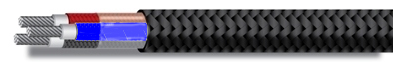
| Shield: | - 5 mil annealed bare copper tape with 25% overlap - Color coded polymeric identification tape laid under the shield: black, red, & blue |
| Grounding Conductor: | - Three split Class B stranded bare annealed copper grounding conductors - Sized in accordance with UL 1072 and NEC Article 250 |
| Cable Assembly: | - Insulated and grounding conductors are cabled together with non-hygroscopic fillers when required - Binder tape is applied over the cabled core |
| Armor: | - Impervious, continuously welded and corrugated aluminum alloy sheath |
| Jacket: | - Flame-retardant, moisture and sunlight resistant PVC, yellow - Low temperature performance meets ASTM D746 brittleness temperature at or below 40°C |
Applications:
- Variable Frequency Drives: 3-conductor CCW armored cables with 3 symmetrical grounding wire are the preferred wiring method for use with AC motors controlled by pulse-width modulated inverters in VFD applications
- For use in feeders and branch circuits in industrial power distribution systems per NEC articles 328 and 330
- Approved for Classes I, II and III, Divisions 1 and 2; and Class I, Zones 1 and 2, hazardous locations covered under NEC Articles 501, 502, and 503.
- Installed on metal racks, troughs, in raceways, in cable trays or secured to supports spaced no more than 6 feet apart
- Installed in both exposed and concealed work, wet or dry locations, directly buried or embedded in concrete
Features:
- For use in feeders and branch circuits in industrial power distribution systems per NEC articles 328 and 330
- Approved for Classes I, II and III, Divisions 1 and 2; and Class I, Zones 1 and 2, hazardous locations covered under NEC Articles 501, 502, and 503.
- Installed on metal racks, troughs, in raceways, in cable trays or secured to supports spaced no more than 6 feet apart
- Installed in both exposed and concealed work, wet or dry locations, directly buried or embedded in concrete
- Cable meets cold impact at -40°C
- 105°C continuous operating temperature, wet or dry
- 140°C emergency rating
- 250°C short circuit rating
- 105°C continuous operating temperature, wet or dry
- 140°C emergency rating
- 250°C short circuit rating
| Part # | AWG Size | No. of Cond. | Grd. Size | Nom. Insul. Thick. | Nom. O.D. | Lbs./M’ | |
| Armor | Overall | ||||||
| 1XMVE20403 | 4 | 3 | 3 × 10AWG | .115” | 1.51” | 1.65” | 1418 |
| 1XMVE20203 | 2 | 3 | 3 × 10AWG | .115” | 1.64” | 1.78” | 1731 |
| 1XMVE21/003 | 1/0 | 3 | 3 × 8AWG | .115” | 1.78” | 1.91” | 2259 |
| 1XMVE22/003 | 2/0 | 3 | 3 × 8AWG | .115” | 1.92” | 2.05” | 2626 |
| 1XMVE24/003 | 4/0 | 3 | 3 × 7AWG | .115” | 2.15” | 2.28” | 3650 |
| 1XMVE225003 | 250 | 3 | 3 × 7AWG | .115” | 2.23” | 2.36” | 4060 |
| 1XMVE235003 | 350 | 3 | 3 × 6AWG | .115” | 2.45” | 2.61” | 5045 |
| 1XMVE250003 | 500 | 3 | 3 × 5AWG | .115” | 2.75” | 2.92” | 7137 |
| 1XMVE275003 | 750 | 3 | 3 × 4AWG | .115” | 3.32” | 3.50” | 10268 |